
Introduction
Are you interested in how one of the most omnipresent encryption algorithms in the world works on the deepest level? Take a look at my take on writing AES encryption algorithm with 128 bit key and ECB mode.
AES (Advanced Encryption Standard) is a modern successor to the older DES (Data Encryption Standard), born out of a 1997 competition hosted by the U.S. National Institute of Standards and Technology (NIST). The Belgian cryptographers Joan Daemen and Vincent Rijmen (ex. 1) submitted the winning design called Rijndael, which officially became the AES standard in 2001. Today, AES is practically everywhere – securing wireless networks, online banking, VPNs, file encryption, and more – due to its efficiency, flexibility, and resilience against attacks.

Why bother writing your own AES-128 implementation from scratch when libraries and hardware acceleration already exist? I feel like nothing beats the clarity and understanding that comes from writing your own code that performs every step of the process. It is both fantastic way of sharpening low-level programming skills and deepen your appreciation for such sophisticated mathematical creation.
How does AES work: High-level overview
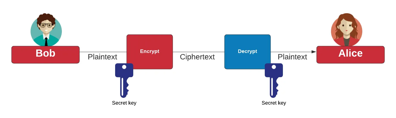
AES is a symmetric encryption algorithm, which means the same key is used for both encrypting and decrypting data. In other words, if you have the key, you can perform both operations. Internally, AES encrypts data in 128-bit ‘blocks’ by repeatedly applying a series of transformations (rounds), each involving substitutions, permutations, and mixing operations with the key. This layered approach makes it extremely difficult to recover the original message without the correct key – making AES both efficient and secure.
Understanding the algorithm as a whole can be quite challenging so let’s break it down – What do we need to do to implement it?
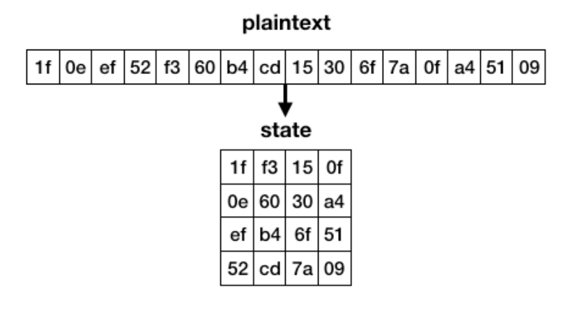
**State – When entering the AES algorithm, a plaintext of 16 bytes gets transformed into a 4×4 square. This state is then encrypted, and finally transformed into a 16-byte ciphertext.
Step 1: Key Expansion – round keys are derived from the cipher key using the AES key schedule. AES requires a separate 128-bit round key block for each round plus one more.
Step 2: Initial round key addition – a round key (128 bit) is applied to the **state (128 bit block of the message) by a simple bitwise XOR operation
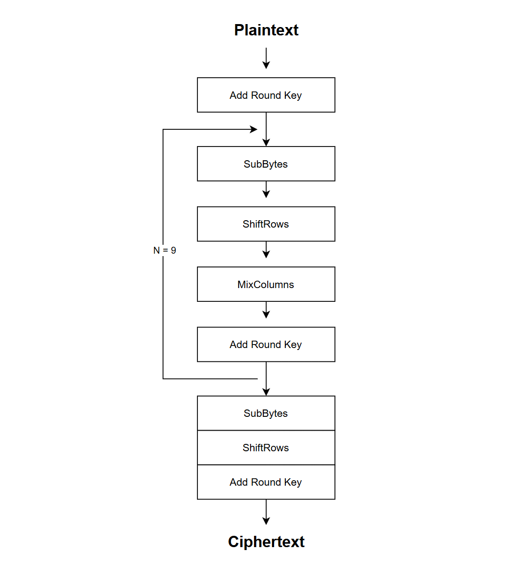
Step 3: Encryption of the 128 bit message block – In case of 128 bit key, there are 9 rounds of 4 different state transformation functions. This includes:
Step 4: Final round (making 10 rounds in total). It consists of the above **state transformation functions, omitting the MixColumns operation.
Below is a diagram for all 10 rounds, encrypting 128 bit block (ex. 4).
In order to fully follow the process I really recommend visiting CryptTool website – It will help you visualise each step of the encryption/decryption. You can see the animation here: https://legacy.cryptool.org/en/cto/aes-animation
That’s all for the high-level overview of the encryption process. In order to implement it we need to dive a little deeper into each step and state transformation function. Let’s jump to the coding part.
Coding the transformation functions: step-by-step
Below you will find my implementation of the 4 main functions that transform the state matrix into the ciphertext. I deliberately omit the function that creates the key schedule (step 1) – I’d like to focus on the main part first.
Due to the fact that all 4 functions alter the state I’ve declared it as a 2D array of size [number of rows] x [number of columns]. Each value is 1 byte so I used 8 bit unsigned integer type (uint8_t).
uint8_t state[num_row][num_col];SubBytes
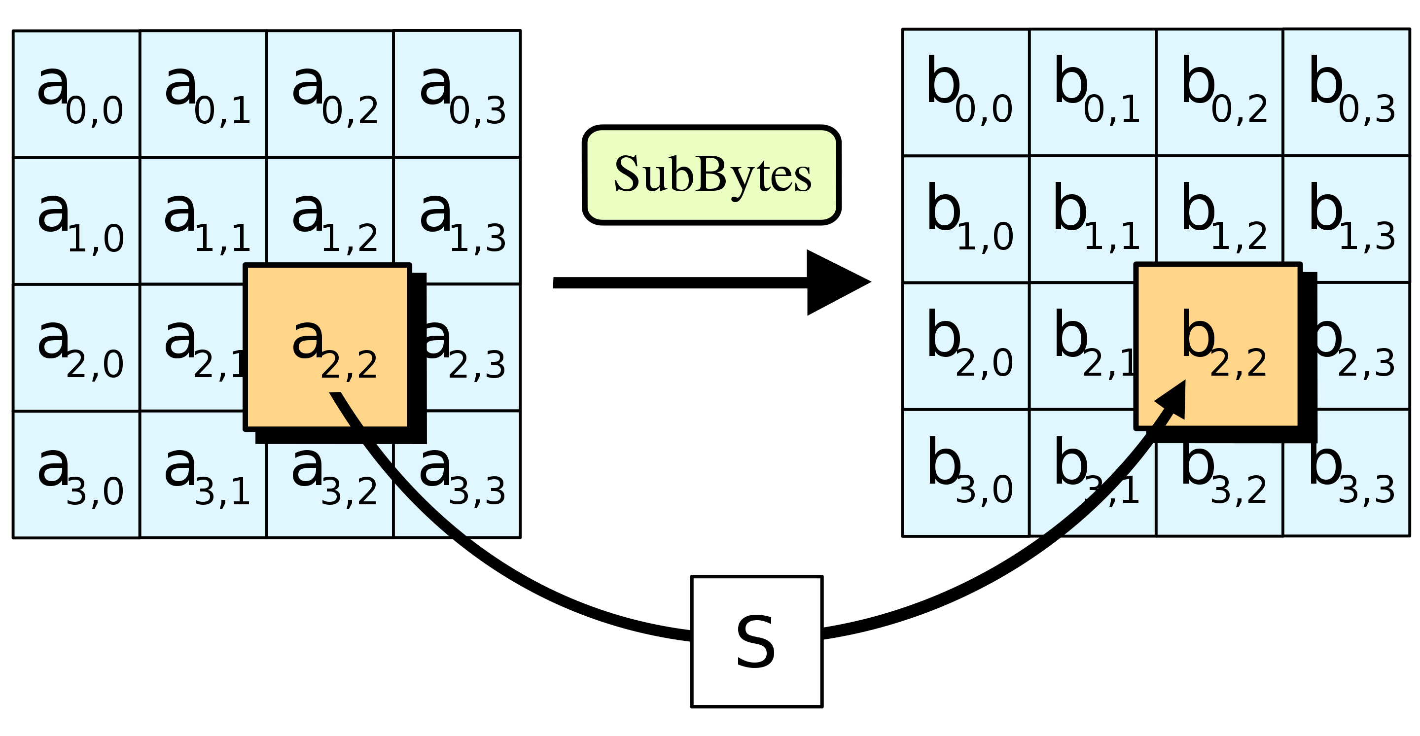
SubBytes function is quite straightforward. The goal is to substitute each individual byte in the state matrix to its pre-defined equivalent (since the name SubBytes). The specific byte-to-byte mapping is designed to introduce non-linear confusion in the data.
There are only 256 possibilities for an 8 bit value so we can declare and initialize a pre-defined array that will help us substitute every byte in any given state. Here is the implementation (ex. 5).
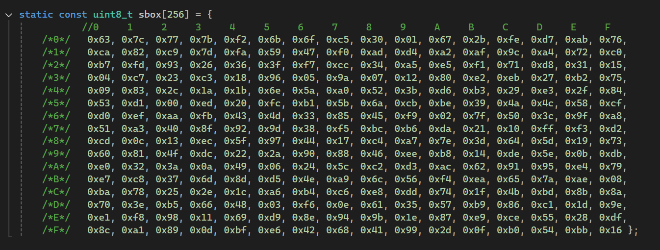
In this array every value is organized so when the algorithm needs substitute value for e.g. „10” it will get the 11th element of the sbox array (or index 10 in other words). The same goes for hex – 0xA index of sbox array stores the substitution value for 0xA which if you look it up is 0x67 (103 in decimal).
In order to be able to retrieve the values, we need a helper function like such:
uint8_t getSBoxValue(uint8_t number) {

    return sbox[number];

}
getSBoxValue takes in an 8 bit value and returns a substitution 8 bit value from the sbox array – simple as that.
Now that we have the state, sbox and the helper (getSBoxValue) function all that is left to do is to iterate through the 2d state array and use the helper function to substitute the values.
void SubBytes()
{

    int i = 0;

    for (; i < num_row; i++) {

        for (int j = 0; j < num_col; j++) {

            state[i][j] = getSBoxValue(state[i][j]);

        }


    }
}
The first for loop iterates through the rows, and the second nested for loop iterates through the columns like so:
State [0][0]
State [0][1]
State [0][2]
State [0][3]
State [1][0]
State [1][1]
...
When all 16 values in the matrix get substituted it’s time for the next function – ShiftRows
ShiftRows
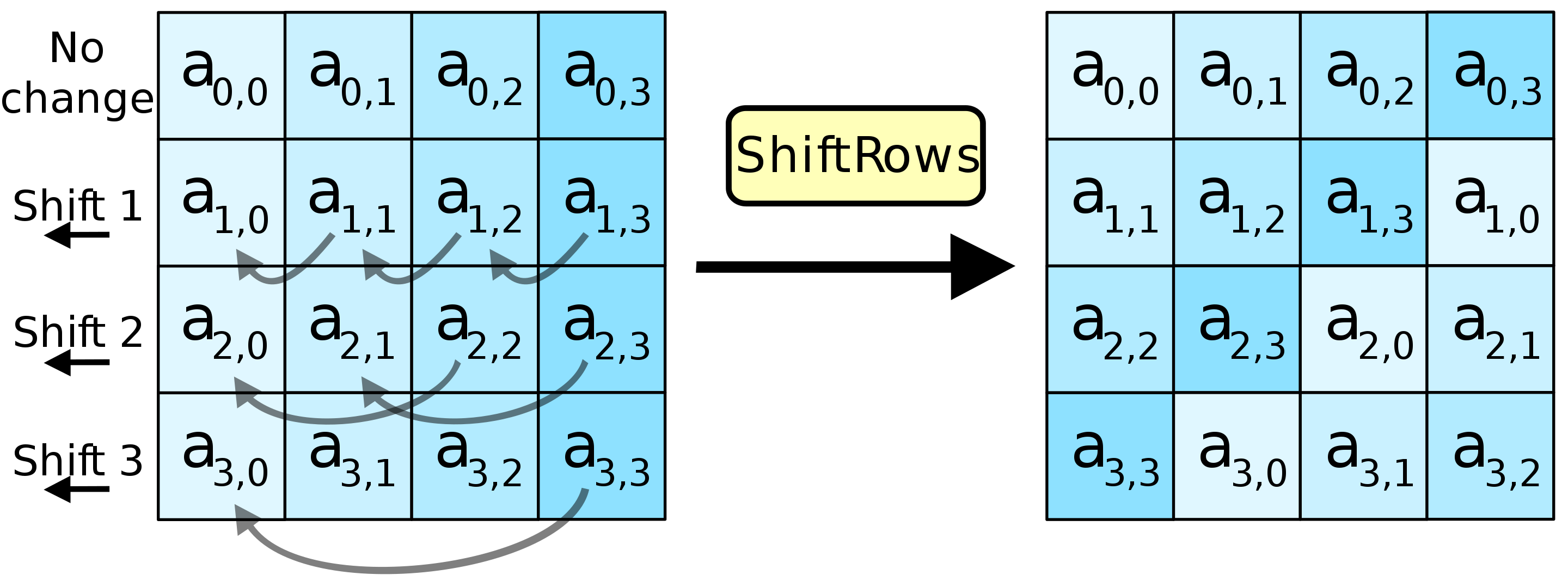
The ShiftRows step operates on the rows of the state it cyclically shifts the bytes in each row by a certain offset. The first row remains the same. Each byte of the second row is shifted one to the left. Similarly, the third and fourth rows are shifted by offsets of two and three respectively. The importance of this step is to avoid the columns being encrypted independently, in which case AES would degenerate into four independent block ciphers.
Before shifting logic, I declared a temp variable that will hold one byte in order not to overwrite any data when performing the operation.
uint8_t temp;With that we are ready to shift every byte in the second row of the state matrix. The logic here is simple: I save the first byte to the temp variable and then assign the value of the second to the first, third to the second etc. Lastly the temp holding the original first byte of the row is assigned in the last (fourth) byte’s place.
//Shift 2nd row 1 left

temp = state[1][0];              // saving 1st value not to overwrite it
state[1][0] = state[1][1];       // assigning 2nd value to the 1st place
state[1][1] = state[1][2];       // assigning 3rd value to the 2nd place
state[1][2] = state[1][3];       // assigning 4th value to the 3rd place
state[1][3] = temp;              // assigning the 1st value to the 4th place
The next step is to shift the 3rd row 2 positions left. I do it in two steps swapping two individual bytes at a time, like so:
//Shift 3rd row 2 left

temp = state[2][0];               // saving 1st value not to overwrite it
state[2][0] = state[2][2];        // assigning the 3rd value to the 1st place
state[2][2] = temp;               // assigning the 1st value to the 3rd place

temp = state[2][1];               // saving 2nd value not to overwrite it
state[2][1] = state[2][3];        // assigning the 4th value to the 2nd place
state[2][3] = temp;               // assigning the 2nd value to the 4th place
Last row needs to be shifted 3 positions left but it is the same as 1 right so I will do it analogically to the first example.
//Shift 4th row 3 left (which is the same as 1 right)

temp = state[3][0];              // saving 1st value not to overwrite it
state[3][0] = state[3][3];       // assigning the 4th value to the 1st place
state[3][3] = state[3][2];       // assigning the 3rd value to the 4th place
state[3][2] = state[3][1];       // assigning the 2nd value to the 3rd place
state[3][1] = temp;              // assigning the 1st value to the 2nd place
That’s it! Now all the rows are correctly shifted and it’s time for the MixColumns function.
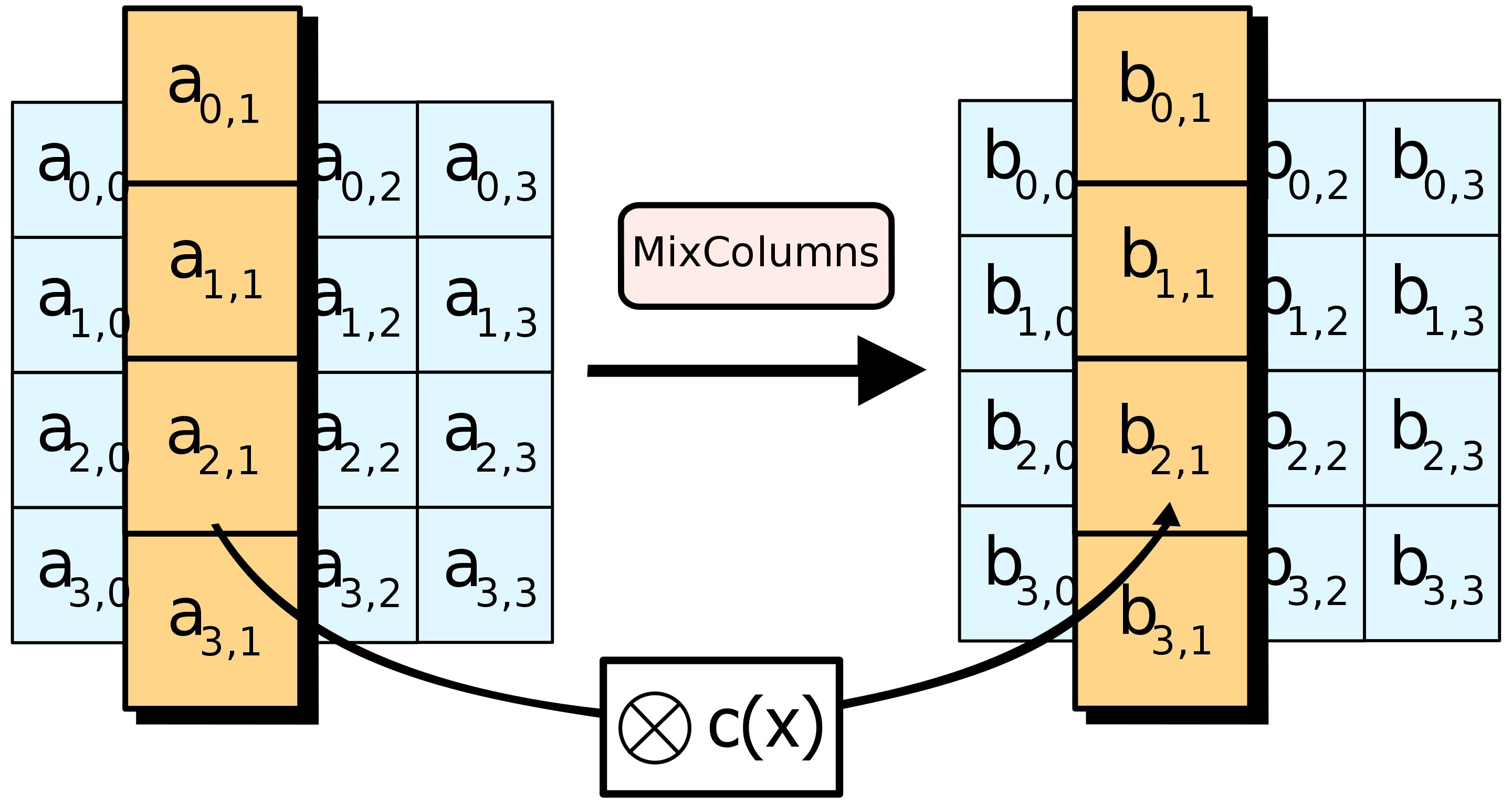
MixColumns
This part is where I had to really use my imagination to understand what is going on. I won’t dive deep into how matrix multiplication in finite fields works because it would be another lengthy article. The goal of this function is to make every byte dependant on every other byte in the same column. Used alongside the previous function (ShiftRows) way we achieve something called diffusion.
To achieve the goal we need to perform two operations on the bytes in each column. The first is multiplication, and the second is addition – sounds quite easy right? The „tricky” part is that when talking about these operations in context of the Galois Field, multiplication is done on polynomial equivalents of the values and addition is equivalent to XOR operation.
When multiplying within GF(2^8) we want to view the byte as a polynomial e.g. Binary value of 1010 0000 is x7 + x5 because only the 7 and 5 powers of 2 are present. We also want to stay inside the 8 bit range and we can do that by using modulo operation (which is essentially an XOR operation with an irreducible polynomial).
For encryption itself we only use multiplication by 2 and 3. Multiplication by 2 is easy to understand because the value „2” can be interpreted as x1 = x. Let’s look at an example:
(x6 + x1) ⋅ x = x7 + x2
If you know binary operations you probably noticed that this operation is the same as performing left shift on the binary value.
When it comes to multiplying by 3 we will apply this rule:
x ⋅ 3 = x ⋅ 2 + x
Knowing that multiplication by 2 is left shift and addition is replaced with XOR (⊕) so we are left with
(left shift x) ⊕ x
Here are the oversimplified rules:
Now that we know the rules, we can implement the matrix multiplication. In MixColumns a fixed matrix is used (ex. 6).
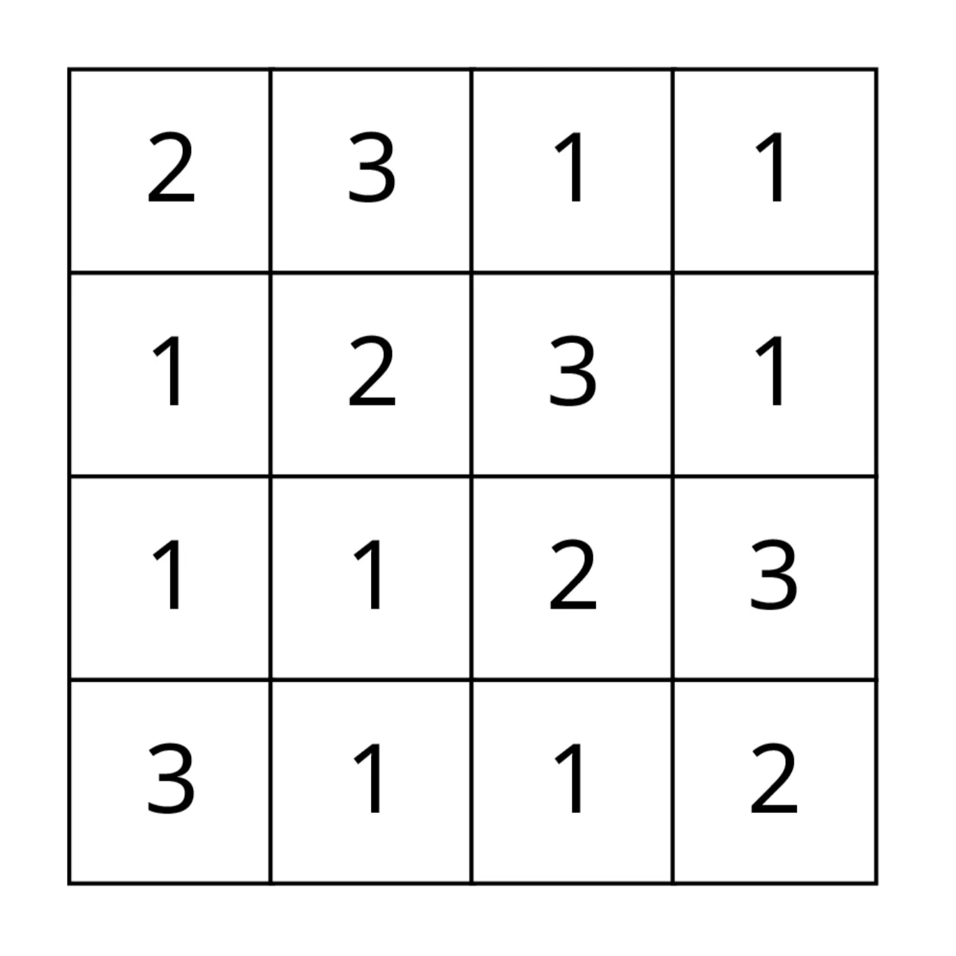
To keep things clean I’ve created two helper functions. One for multiplying by 2 and modulo operation and the second one for multiplying by 3 and returning results.
Below xtime function is using left shift to multiply x by 2 and then checks if the original value of x has the most significant bit set – if yes the result of multiplication is larger than 28 and we need to XOR it with the irreducible polynomial which in this case is in hex value 0x1B
uint8_t xtime(uint8_t x) {
    return (x << 1) ^ ((x & 0x80) ? 0x1B : 0x00);
}
The multiply function returns the correct values based on the provided multiplier.
uint8_t multiply(uint8_t x, uint8_t multiplier) {
    if (multiplier == 0x01) return x;
    if (multiplier == 0x02) return xtime(x);
    if (multiplier == 0x03) return xtime(x) ^ x;
}
And now for the MixColumns itself
void MixColumns() {

    for (int i = 0; i < 4; i++) {

        uint8_t s0 = state[0][i];
        uint8_t s1 = state[1][i];
        uint8_t s2 = state[2][i];
        uint8_t s3 = state[3][i];

        // Matrix multiplication
        state[0][i] = multiply(s0, 0x02) ^ multiply(s1, 0x03) ^ s2 ^ s3;
        state[1][i] = s0 ^ multiply(s1, 0x02) ^ multiply(s2, 0x03) ^ s3;
        state[2][i] = s0 ^ s1 ^ multiply(s2, 0x02) ^ multiply(s3, 0x03);
        state[3][i] = multiply(s0, 0x03) ^ s1 ^ s2 ^ multiply(s3, 0x02);

    }
}
s0-s3 are temporary buffers for the bytes in each column and after being modified they are assigned back to the original state matrix.
Key Schedule
Before I show how a round key is added, we must first cover key schedule (expansion).
The „key schedule” is the process by which the cipher key gets expanded into a set of round keys. This happens before the encryption/decryption process. The overall number of resulting round key bits is equal to the block length multiplied by the number of rounds plus one (here 128 bit * 11 = 1408 bit).
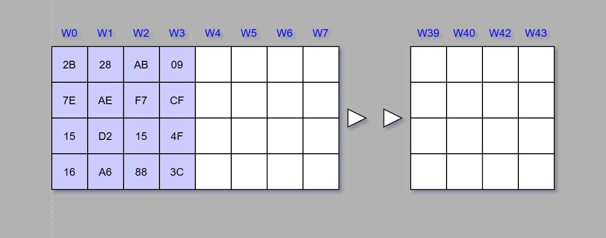
The expanded key can be seen as an array of 4 byte words (columns marked as W on the diagram), numbered from 0 to 43. The first four columns are filled with the given 128 bit cipher key (ex. 7).
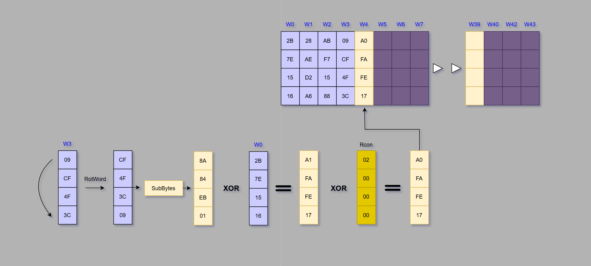
Every fourth word is created by taking the previous column (W-1), rotating the first byte to the bottom, performing SubBytes, XOR operation with the (W-4) column, and lastly XOR with round constant (Rcon).
Below is an example based on W4 column.
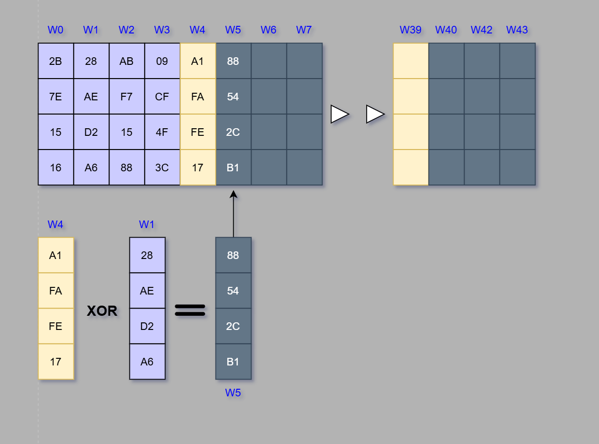
Every other column is a result of an XOR operation of W-1 and W-4 columns. Below is an example based on the W5 column.
This exact procedure is repeated until filling the whole 176 bytes (44 words) needed for all 10 rounds of matrix transformation and one additional AddRoundKey operation at the start.
In my implementation, I created a CreateKeySchedule function that does the key expansion. To keep the demonstration clear I will be showing only the code behind words that are not multiple of 4 (e.g. w5, w6, …)
void CreateKeySchedule(const uint8_t* key) {

int i = 0;

    for (; i < (num_col * (num_rounds + 1)); i++)
    {

            // create a normal word by performing: (W-1) XOR (W-4)

            rkey[i * 4 + 0] = rkey[(i - 1) * num_col + 0] ^ rkey[(i - 4) * num_col + 0];
            rkey[i * 4 + 1] = rkey[(i - 1) * num_col + 1] ^ rkey[(i - 4) * num_col + 1];
            rkey[i * 4 + 2] = rkey[(i - 1) * num_col + 2] ^ rkey[(i - 4) * num_col + 2];
            rkey[i * 4 + 3] = rkey[(i - 1) * num_col + 3] ^ rkey[(i - 4) * num_col + 3];

        }

}
The rkey is a 176 byte array where the first 16 bytes hold the original key. The „i” integer is for keeping the word Wi count.
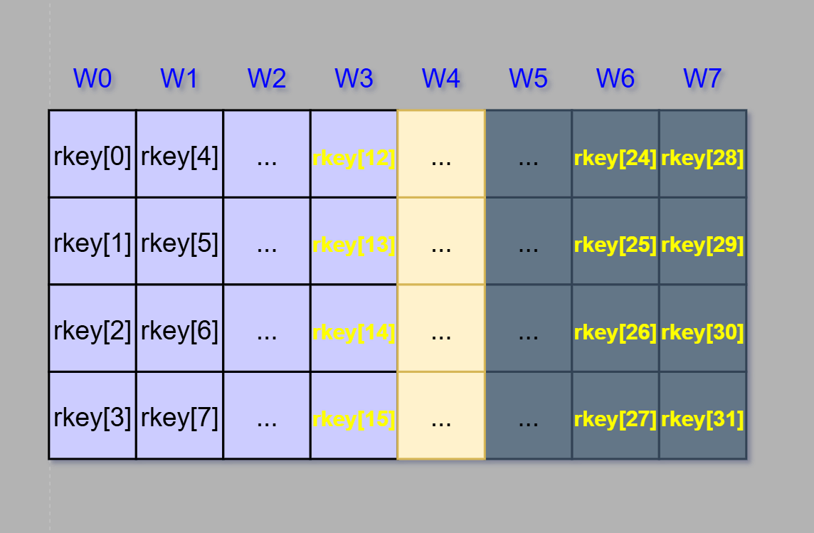
Let’s say we want to create W7 word. We need to XOR W6 and W3 words. Take a look below on how the function would do that.
rkey[28] = rkey[24] ^ rkey[12];
rkey[29] = rkey[25] ^ rkey[13];
rkey[30] = rkey[26] ^ rkey[14];
rkey[31] = rkey[27] ^ rkey[15];
That translates to: Bytes 28-31 (W7) are equal to bytes 24-27 (W6) XOR’ed with bytes 12-15 (W3)
AddRoundKey
In the AddRoundKey step, the goal is to XOR the current 16 bytes of state matrix with a corresponding 16 bytes of the subkey (created in the KeySchedule step). The implementation is straightforward:
void AddRoundKey(uint8_t round) {

    for (int i = 0; i < num_row; i++) {

        for (int j = 0; j < num_col; j++) {

            state[j][i] ^= rkey[round * num_col * num_row + i * num_col + j];

        }

    }

}
There are two for loops that move through the state matrix from byte 0 to 15. The state matrix is updated by performing XOR operation on the current byte and the corresponding key byte. To see if the calculations of the rkey index are correct, we can test it.
Let’s say we are in the 5th round and we want to add the subkey to the first byte of the state – state [0][0]
round = 5
i = 0
j = 0

state [0][0] ^= rkey[5 * (4 * 4) + (0 * 4) + 0 ]
state [0][0] ^= rkey[80]
That is correct, if there were 4 rounds already and one AddRoundKey operation at the start, that means we moved 16 ⋅ 5 = 80 bytes
Alright, those are all the transformation functions we need to encrypt some data! Let’s use them to create a single function that will encrypt any plaintext we want.
AES128_Encrypt
This function will be the „black box” that handles the encryption when fed data and 128 bit key.
Function Signature & Basic Parameters
int AES128_Encrypt(const uint8_t* key, uint8_t* input, size_t in_size, uint8_t* output, size_t out_size)The function returns integer which will be used for success or error codes. As the arguments it takes:
To have some guardrails when working with buffers it’s important to check their sizes and manage the memory accordingly, hence the amount of total arguments needed.
Block Alignment & Padding
Padding the data before encryption is crucial because AES works with 128 bit blocks – the data itself must be multiple of 128 bit (16 byte).
There are two most common padding methods:
To keep things simple I implemented the zero padding method. To do that, we first need to align the size to 16 byte block and then calculate how much padding we need.
size_t aligned_size = (in_size + 15) & ~15;
size_t padding_size = aligned_size - in_size;
Similarly to the article where I wrote a memory allocator I used the AND NOT bitwise operation. It „masks” out the 4 least significant bits (which are 15 in decimal). When a 15 is added prior to this operation, we are always left with the nearest and the smallest multiple of 16.
The padding size is simply calculated by subtracting the provided input buffer size (in_size) from the aligned size.
The padding logic itself is a very straightforward operation and It won’t be included here.
Temporary buffer & Key Schedule Creation
In order to be able to freely manipulate the data (e.g. add padding), we need to create a temporary buffer for the plaintext. Here I used malloc to allocate it dynamically.
uint8_t* data_buffer = malloc(aligned_size);The next step is to copy the data into the buffer.
memcpy_s(data_buffer, aligned_size, input, in_size);Finally, we have to expand the 128 bit key by passing it to the earlier created function.
CreateKeySchedule(key);Loading Data Into The State Matrix
Before starting the encryption flow we need to fill the state matrix with 16 bytes of data. This can be done using nested for loops
for (int col = 0; col < num_col; col++)
{

        for (int row = 0; row < num_row; row++)
        {
            state[row][col] = data_buffer[i + (col * 4) + row];
        }

}
The data is filled with rows being the first – we need to keep this in mind to later unload it correctly. When calculating index for data_buffer the „i” is an integer that always „points” to the first byte of the currently modified state (e.g. 16, 32, 48 … ).
The col * 4 statement moves us to correct column and row to the correct row.
Encrypting The State Matrix
To encrypt the state we first need to create a counter that will keep the information about round number.
int round = 0;Now, following the standard AES encryption flow, the key needs to be added to the state. Next the 9 main rounds of SubBytes, ShiftRows, MixColumns and AddRoundKey functions transform the state. Final (10th) round omits the MixColumns step.
 AddRoundKey(round);

    //Next 9 rounds are identical
    for (round = 1; round < 10; round++)
    {

        SubBytes();
        ShiftRows();
        MixColumns();
        AddRoundKey(round);

    }

    //Final round
    SubBytes();
    ShiftRows();
    AddRoundKey(round);
When this process is finished, we are left with an encrypted 128-bit block of state matrix. The last thing to do is to unload it to the output buffer and prepare for the next loop (if there is any data left to encrypt).
Offloading Data Into The Output Buffer
Moving the data from the state matrix is identical to loading it when it comes to loops. The only difference is the direction of moving the data.
output[i + (col * 4) + row] = state[row][col];Here it is – the data is now protected with the power of AES encryption algorithm! In the next section I will show the algorithm in action.
Testing the algorithm
To test the algorithm, we need to verify it against standard AES test vectors and compare the results with those from well-established implementations. Additionally, it’s important to check edge cases, such as an all-zero input. While this article focuses on encryption, I will also include decryption results, as a working AES implementation must support both operations.
Standard AES Test Vectors (NIST)
For the standard vectors I will be using F.1.1 ECB-AES128.Encrypt from the National Institute of Standards and Technology (NIST) documentation (ex. 11).
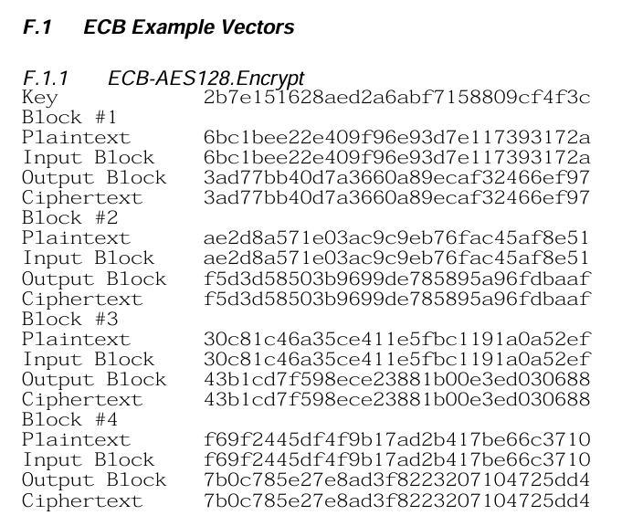
Block #1 and Block #2 should be enough for showcasing purposes. I initialize the key as an uint8_t 16 byte array.
const static uint8_t mykey[16] = {
                                   0x2B, 0x7E, 0x15, 0x16,
                                   0x28, 0xAE, 0xD2, 0xA6,
                                   0xAB, 0xF7, 0x15, 0x88,
                                   0x09, 0xCF, 0x4F, 0x3C
                                 };
Similarly to the key, I provide the data as 32 byte array (2 blocks) like so:
uint8_t confidential_hex[32] = { 0x6b, 0xc1, 0xbe, 0xe2, 0x2e, 0x40, 0x9f, 0x96, 0xe9, 0x3d, 0x7e, 0x11, 0x73, 0x93, 0x17, 0x2a, 0xae, 0x2d, 0x8a, 0x57, 0x1e, 0x03, 0xac, 0x9c, 0x9e, 0xb7, 0x6f, 0xac, 0x45, 0xaf, 0x8e, 0x51 };Next I call AES128_Encrypt.
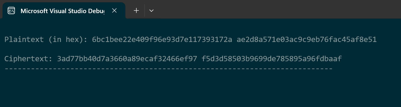
AES128_Encrypt(mykey, confidential_hex, confidential_size, output_buffer, output_size);After displaying the plaintext and ciphertext in the console and cross-referencing it with the NIST documentation, it seems to be correct.
ASCII Plaintext Encryption, Padding, Decryption Test
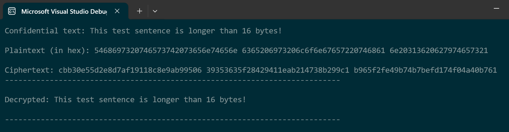
I feel like the most satisfying (and relatable) way for checking the algorithm is by encrypting the plaintext in human readable form. This test will also require the plaintext to be padded and decrypted.
We’ll be encrypting a sentence that will take more than one block and it will not be multiple of 16 bytes which should be detected and resolved accordingly by using zero-padding. After encrypting, the cipher text will be decrypted back to the original plaintext form.
Input:
Output:
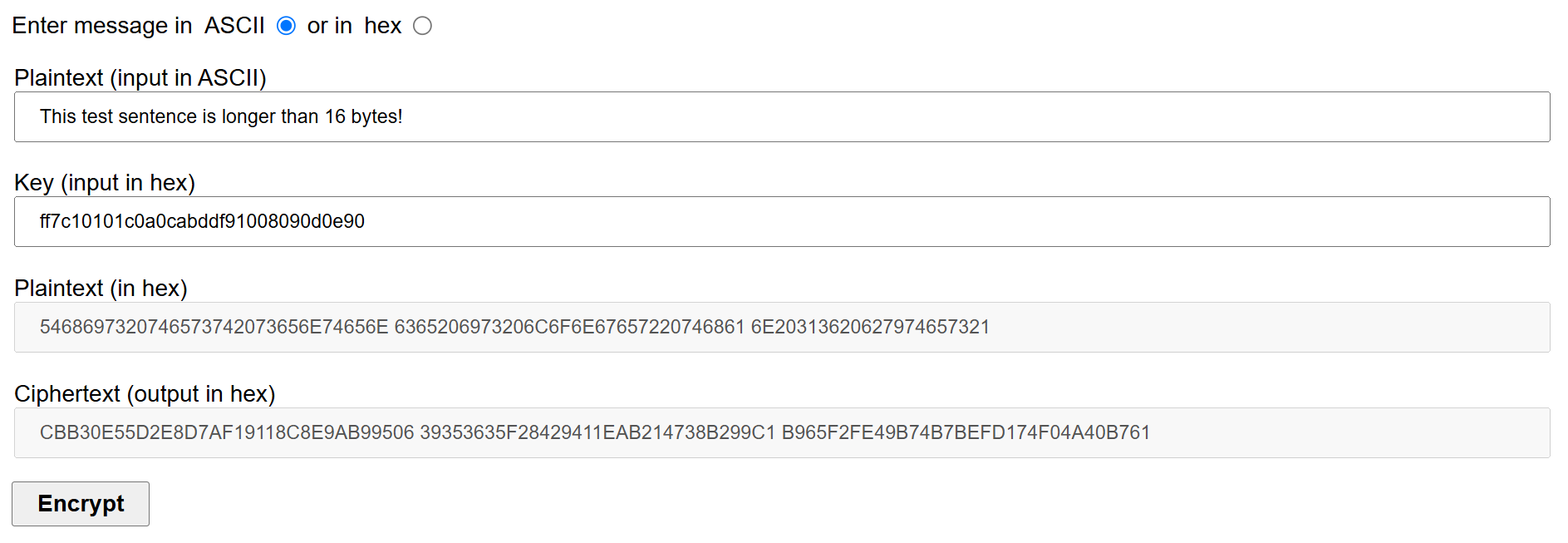
To be completely sure that we are seeing the correct result, I used CryptTool website for cross reference:
Edge Case: All zero plaintext
As a last test I decided to use all zero plaintext.
Input:
Output:
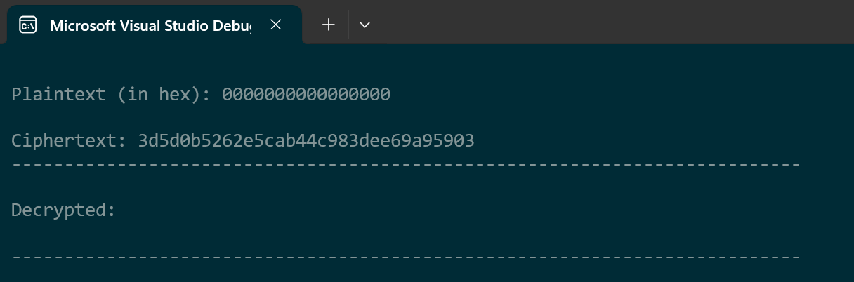
Again checking with the CryptTool:
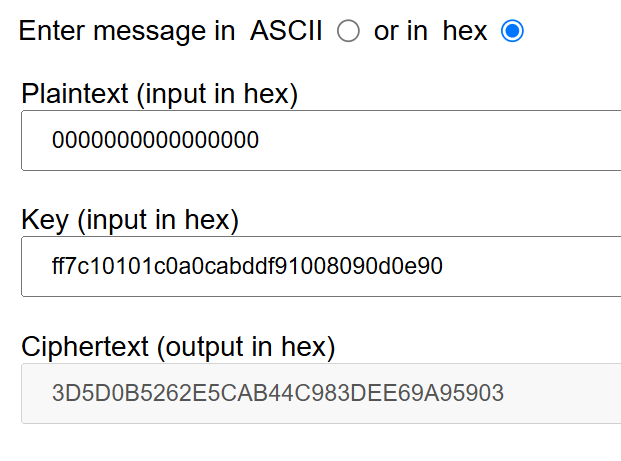
Everything seems to be working perfectly. Let’s move to the summary section.
Summary
In this article, we explored the inner workings of AES-128 encryption, implementing it from scratch to gain a deeper understanding of its transformation processes. We covered key steps such as SubBytes, ShiftRows, MixColumns, and AddRoundKey, as well as the crucial key expansion process.
To validate the implementation, we tested it against NIST standard test vectors, an ASCII plaintext input with padding and decryption, and an edge case of an all-zero plaintext. The results matched known outputs, confirming that this AES-128 implementation functions correctly.
While the implementation successfully encrypts and decrypts data, it’s important to note that using ECB mode has significant security weaknesses. Since identical plaintext blocks produce identical ciphertext blocks, patterns in the data remain visible, making it vulnerable to attacks. In real-world applications, CBC (Cipher Block Chaining) or GCM (Galois/Counter Mode) is preferred for stronger security.
By writing AES-128 from scratch, I not only built a working encryption function but also gained a deeper appreciation for the complexity and elegance of modern cryptography.